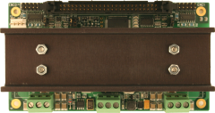
The 7I29 is 2 channel H-bridge motor drivers for the 4I27 or FPGA based motor controller cards. The 7I29 connects to the motor controller card with a 50 conductor flat cable and have screw terminals for motor power and motor connections. Two 7I29s can share a 4 Axis 50 conductor cable to FPGA controller. Encoder and index input connectors are also made available on the 7I29. Encoder inputs can be single ended or differential. The 7I29 has overcurrent and overtemperature protection. The 7I29 is rated at 22.5A continuous per channel at 165V maximum input voltage. Input signals have 2500V RMS isolation from motor power.
7I29 DATA SHEET ---
7I29
MANUAL
7I30 Quad 100 Watt H-bridges for 4I27,4I34,4I65,5I20,7I60
 The 7I30 is a 3A, 36V 4 channel H-bridge motor driver for the
4I27,
4I34, 4I65, 5I20 and 7I60 motion controllers. They use high efficiency
synchronous rectifying drivers, eliminating the need for heat sinks.
They connect to the motion controller card with a 50 conductor flat
cable and have AMP Mini Mate-N-Lock connectors for motor drive and
encoder/index connections. Each channel has a selectable 3A or 1A
current limit and can operate in fast decay or slow decay mode. Input
RC
filters and Schmitt triggers are provided for encoder and index
signals.
The 7I30 is available with 50 pin male header for use with
flat
cable connection to 4I27, 4I34, 4I65, 4I68, 5I20, 7I60 or a 50 pin
female
header on the reverse side for use as a 7I60 daughter card. A 2 channel
version (7I30-2) is available for use with the 4I27.
The 7I30 is a 3A, 36V 4 channel H-bridge motor driver for the
4I27,
4I34, 4I65, 5I20 and 7I60 motion controllers. They use high efficiency
synchronous rectifying drivers, eliminating the need for heat sinks.
They connect to the motion controller card with a 50 conductor flat
cable and have AMP Mini Mate-N-Lock connectors for motor drive and
encoder/index connections. Each channel has a selectable 3A or 1A
current limit and can operate in fast decay or slow decay mode. Input
RC
filters and Schmitt triggers are provided for encoder and index
signals.
The 7I30 is available with 50 pin male header for use with
flat
cable connection to 4I27, 4I34, 4I65, 4I68, 5I20, 7I60 or a 50 pin
female
header on the reverse side for use as a 7I60 daughter card. A 2 channel
version (7I30-2) is available for use with the 4I27.
7I54 Six channel 3A 40V Servo interface
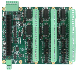 The 7I54 is a low cost 6 Axis H-bridge card for use with Mesa motion
control cards. The 7I54 has a maximum per axis current rating of 3 Amps
and a voltage rating of 40V. Current limits of 1 Amp and 3 Amp are user
selectable, as are voltage and current (torque) modes. All motor power
circuitry is galvanically isolated from the controller interface.The
H-bridge chips (Allegro A3959) use DMOS transistors and synchronous
rectification for high efficiency and low power dissipation. PWM rates
up to 50 KHz are supported. The 7I54 also conditions and
multiplexes the encoder input signals and supports both TTL and
differential encoder inputs. The controller connection is a 50 pin
header that matches the pinout of the Mesa 50 pin FPGA based motion
controllers. The 7I54 uses Phoenix compatible 3.5 mm headers and is
supplied with pluggable terminal blocks.
The 7I54 is a low cost 6 Axis H-bridge card for use with Mesa motion
control cards. The 7I54 has a maximum per axis current rating of 3 Amps
and a voltage rating of 40V. Current limits of 1 Amp and 3 Amp are user
selectable, as are voltage and current (torque) modes. All motor power
circuitry is galvanically isolated from the controller interface.The
H-bridge chips (Allegro A3959) use DMOS transistors and synchronous
rectification for high efficiency and low power dissipation. PWM rates
up to 50 KHz are supported. The 7I54 also conditions and
multiplexes the encoder input signals and supports both TTL and
differential encoder inputs. The controller connection is a 50 pin
header that matches the pinout of the Mesa 50 pin FPGA based motion
controllers. The 7I54 uses Phoenix compatible 3.5 mm headers and is
supplied with pluggable terminal blocks.
7I32 Dual 1/2 to 3A stepper driver
The 7I32 is a 3A, 36V 2 channel current feedback microstep (up to 256 uSteps/ step) capable stepper motor driver for the Anything I/O series of FPGA based I/O cards. They use high efficiency synchronous rectifying drivers, eliminating the need for heat sinks. They connect to the motion controller card with a 50 conductor flat cable and have AMP Mini Mate-N-Lock connectors for step motor drive and encoder/index connections. Input RC filters and Schmitt triggers are provided for encoder and index signals. The 7I32 is available with 50 pin male header for use with flat cable connection to 4I34, 4I65, 4I68, 5I20, 7I60 or a 50 pin female header on the reverse side for use as a 7I60 daughter card.
DATA SHEET --- 7I32 MANUAL8I20 2200W 3 Phase Amplifier
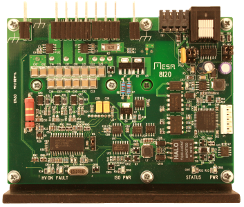
The 8I20 is a low cost 2200W 400V three phase torque
mode
amplifier for synchronous permanent magnet servo motors (Brushless AC
servo) up to approximately 3HP. The 8I20 will supply peak currents of
30A. High side logic and gate power are derived from the low side
allowing a wide operational bus voltage range (24 to 400VDC) and host
communication when bus voltage is off. Low side power can be 5V +-5% or
7-48V unregulated. 3750V RMS isolation is provided between high and low
side electronics. Hall effect current sensing is used along with high
speed bus voltage monitoring for an accurate, stable, and fast
current/torque control loop. High side over current sensing protects
the IGBT module from line-line and line-ground faults. A brake output
capable of 15A drive is provided. The brake output can be driven at a
presettable overvoltage setting. Even though it uses a 40 Mips DSP, the
8I20 is a 'dumb' amplifier suitable for integration in host based
motion control systems. The 8I20 requires reference angle and
requested current/torque values sent from a host controller. The 8I20
uses the requested torque and reference angle to control the current
loop. The 8I20 can echo status information to the host controller
including bus voltage, phase currents, card temperature etc.
The
host controller may be a PC with a fast serial interface and quadrature
counters or a Mesa FPGA card running SoftDMC or HostMot2 firmware. For
applications that require a smart amplifier, the 8C20 daughter card can
be added. The 8I20/8C20 combination adds the features of analog input
velocity and torque modes, step and direction mode,
quadrature
input mode, smart position control mode, and four
isolated
inputs and outputs.
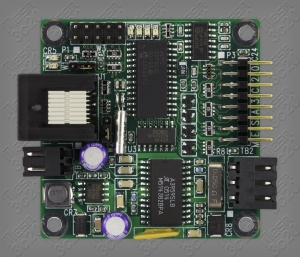
7I39 Dual 250W 3 Phase BLDC driver
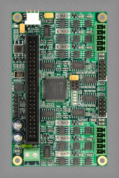
The 7I39 is a Dual 3 Phase bridge driver for
Brushless 3 phase
motors. The 7I39 is available in low voltage and high voltage models.
The low voltage model is rated at 10A 30 VDC per axis while the high
voltage model is rated at 5A 50 VDC per axis. Each 3 Phase bridge on
the 7I39 has selectable overcurrent limits of .75 times and 1.5 times
rated current. An overvoltage clamp protects the 7I39 from inductive
voltage surges, reducing the need for large motor supply capacitors.
Low on resistance MOSFETs and high performance gate
drivers give the 7I39 high efficiency. Gate power is derived from logic
side power so that unlike other bridges, the drivers are functional all
the way down to 0V motor power supply, allowing safe and easy setup and
testing. Encoder and Hall effect inputs are RC filtered and processed
through a Schmitt trigger before being forwarded to the FPGA.
The
7I39 is compatible with the 4I34M, 4I65, 4I68, 5I20 and 7I60 Anything
I/O cards.
DATA SHEET
---
7I39
MANUAL
7I40 Dual 400W driver
The 7I40 is a
Dual H bridge
driver for two brush type motors or other inductive loads. The 7I40 is
available in low voltage and high voltage models(7I40L and 7I40H). The
7I40L is rated at 10A 40 VDC per axis while the 7I40H is rated at 7A 80
VDC per axis. Each bridge on the 7I40 has selectable overcurrent limits
of .75 times and 1.5 times rated current. An overvoltage clamp protects
the 7I40 from inductive voltage surges, reducing the need for large
motor supply capacitors. Low on resistance MOSFETs and high performance
gate drivers give the 7I40 high efficiency and low dead time to support
switching rates up to 100 KHz. Gate power is derived from logic side
power so that unlike other bridges, the drivers are functional all the
way down to 0V motor power supply, allowing safe and easy
initial
setup and testing. The 7I40 also includes encoder input conditioning.
Encoder inputs can be either single ended or differential. The 7I40 is
compatible with the MESA's 4I27 or the 4I34M, 4I65,
4I68,
5I20, 5I22 and 7I60 Anything I/O cards with SoftDMC or HostMot
firmware, or can be used with a customer supplied controller.
The SoftDMC firmware converts any of our FPGA
based I/O
cardsto a high performance DSP based
motion
control system. The SoftDMC system supports up to 8 axis
simultaneous
motion. Features include Position and Velocity control modes,
trapezoidal motion profiles, cubic motion profiles, 32 bit
position range,
32 bit acceleration and velocity parameters, high sample
rates
(>60 KHz for 4 axis, >30 KHz for 8), two quadrature
encoder
inputs
per axis for dual feedback systems, 32 bit gearing, velocity,
acceleration and friction feed forward terms in PID loop,
breakpoint/event logic for flexible real time (within one sample
period)
handling of internal and external events (such as limit switches),
efficient FIFOed host interface with multichannel command queueing, and
much
more. SoftDMC supports Brush motors, 2 phase stepper motors in closed
loop and open loop modes, and 3 phase AC and DC brushless motors in
closed and
open loop modes. The SoftDMC firmware is included
free with all Mesa FPGA
based
cards and can be licensed for a nominal charge for non-Mesa cards and
embedded FPGA designs. SoftDMC is an ideal replacement for LM629 and
other ASIC
based motion controllers, assuring long term availability and ease of
modification due to its open FPGA based design.
7I25/7I27 150/400 Watt H-bridges for 4I27 and FPGA cards
The 7I25 and 7I27 are 2 channel H-bridge motor drivers for the 4I27 motor controller card or the Anything I/O seris of FPGA cards. They connect to the motor controller card with a 50 conductor flat cable and have screw terminals for motor power and motor connections. Encoder and index input connectors are also made available on the 7I25/7I27. Both H-bridges have overcurrent and surge protection. The 7I25 is rated at 3A continuous per channel and 6A peak at 48V maximum input voltage. The 7I27 is rated at 10A continuous and 25A peak at 45V maximum input voltage.
7I27 DATA SHEET --- 7I27 MANUAL 7I25 MANUAL
4I27A 2 axis servo motor controller card (analog out)
The 4I27A is a low cost, LM628 based 2 axis DC servo motor control system implemented on a stackable PC/104 bus card.The 4I27A is designed for high performance positioning systems using DC servo motors with quadrature shaft encoders. The per axis output of the is a +- 10 volt analog signal with 12 bits of resolution. Quadrature encoder and index inputs use balanced RS-422 levels for noise immunity. Control signals for each axis include 3 auxiliary I/O bits. These I/O bits are used for over-temperature shutdown detect and servo amplifier enable. Eight general purpose I/O bits are available for any application use. The LM628's used on the 4I27A are high performance digital processors specifically designed for motion control.The LM628 can execute a ramp-up, slew, and ramp-down motion sequence without host processor intervention. Host interrupts can be generated at end of motion, position breakpoints, index pulse, or in response to various error conditions. Interrupts are or'ed on the 4I27A card, so that only one system interrupt is used. The IRQ line used can be software selected from any of the 11 available AT bus interrupts. The 4I27A requires only +5V power, as all analog output power is generated on card. A digital PID filter is used to set loop feedback parameters for stability and optimum performance. Velocity, target position and filter parameters may be changed during motion. Demonstration software includes examples of 2 axis position mode operation, velocity mode operation, and a simple filter tuning program that allows dynamic filter coefficient modification while providing a graphic display of the servo system step response. Source code is provided for all demonstration software. A PWM output version of the 4I27A is available as the 4I27.
DATA SHEET --- MANUAL---SUPPORT SOFTWARE
The 4I27 is a low cost, LM629 based 2 axis DC servo motor control system implemented on a stackable PC/104 bus card. The 4I27 is designed for high performance positioning systems using DC servo motors with quadrature shaft encoders. The per axis output of the 4I27 is an 8 bit sign-magnitude PWM signal that can drive H-bridge type servo amplifiers directly. Quadrature encoder and index inputs are conditioned with RC filters and Schmitt triggers for noise immunity. RC filter time constants can be changed by replacing a plug-in resistor network. Control signals for each axis include 3 auxiliary I/O bits. These I/O bits are used for over-temperature shutdown detect and H-bridge enable when the 4I27 is used with the 7I25 or 7I27 H-bridge drivers. Eight general purpose I/O bits are available for any application use. The LM629's used on the 4I27 are high performance digital processors specifically designed for motion control. The LM629 can execute a ramp-up, slew, and ramp-down motion sequence without host processor intervention. Host interrupts can be generated at end of motion, position breakpoints, index pulse, or in response to various error conditions. Interrupts are or'ed on the 4I27 card, so that only one system interrupt is used. The IRQ line used can be software selected from any of the 11 available AT bus interrupts. A digital PID filter is used to set loop feedback parameters for stability and optimum performance. Velocity, target position and filter parameters may be changed during motion. The clock speed of the LM629's can be lowered to accommodate large motors that require lower PWM chopping frequencies. Demonstration software includes examples of 2 axis position mode operation, velocity mode operation, and a simple filter tuning program that allows dynamic filter coefficient modification while providing a graphic display of the servo system step response. Source code is provided for all demonstration software. An analog out version of the 4I27 is available as the 4I27A.
DATA SHEET --- MANUAL---SUPPORT SOFTWARE4I28 4 axis servo motor controller card (PWM)
The 4I28 is a low cost, LM629 based 4 axis DC servo motor control system implemented on a stackable PC/104 bus card. The 4I28 is designed for high performance positioning systems using DC servo motors with quadrature shaft encoders. The per axis output of the 4I27 is an 8 bit sign-magnitude PWM signal that can drive H-bridge type servo amplifiers directly. Quadrature encoder and index inputs are conditioned with RC filters and Schmitt triggers for noise immunity. Sixteen general purpose I/O bits are available for any application use. The LM629's used on the 4I28 are high performance digital processors specifically designed for motion control. The LM629 can execute a ramp-up, slew, and ramp-down motion sequence without host processor intervention. Host interrupts can be generated at end of motion, position breakpoints, index pulse, or in response to various error conditions. Interrupts are or'ed on the 4I28 card, so that only one system interrupt is used. A digital PID filter is used to set loop feedback parameters for stability and optimum performance. Velocity, target position and filter parameters may be changed during motion. Demonstration software includes examples of 4 axis position mode operation, velocity mode operation, and a simple filter tuning program that allows dynamic filter coefficient modification while providing a graphic display of the servo system step response. Source code is provided for all demonstration software.
DATA SHEET --- MANUAL---SUPPORT SOFTWARE
The 4I36 is a stackable PC/104 card with eight 32 bit
up/down
counters with quadrature count inputs and per channel index inputs. The
4I36 is intended for robotic, motor control, measurement, and
instrumentation applications. The 4I36 has selectable TTL or RS-422
levels on its quadrature and index inputs. TTL or RS-422 operation is
jumper selectable in groups of two channels. The TTL inputs have pullup
resistors and RC / Schmitt filtering. The differential RS-422 inputs
are
suited for longer cable lengths and have optional termination. 24
general purpose I/O bits capable of sinking 24 mA are provided control
applications. The encoder connectors are compatible with the 4I30, and
the I/O connector is compatible standard I/O module racks. The
4I36 counters can count in normal quadrature mode (4X) or up/down mode.
Digital filtering is used on encoder inputs to reject input noise. The
4I36 counters may cleared
individually, or all counters may be cleared simultaneously. Each
counter has a option to be cleared by either the rising or falling edge
of the index signal. Maximum count rate of the 4I36 with TTL
inputs is 4 million counts per second.
Maximum count rate with RS-422 inputs is 10 million counts per second.
Count range is -2,147,483,648 to +2,147,483,647 or 0 to 4,294,967,295.
Any counter may be configured to provide a timing reference for
velocity
calculations instead of quadrature input. This timing reference is a 32
bit up counter running at 48 MHz +- .01%. The 4I36 is a 16 bit card and
uses an index register to access the many registers on the chip, the
index register has an auto-increment function that allows all 8 of the
32 bit counters to be read in only 17 16 bit I/O read instructions. The
4I36 uses a FPGA chip for
all counting and I/O so can be easily upgraded or modified in the field
for specific requirements. The FPGA configuration flash memory can be
updated from the host, no special cable or adapters are required.
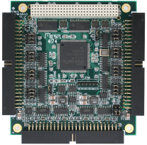
The 4I74 is a stackable PCI/104 card with eight quadrature up/down counters with quadrature count inputs, quadrature edge timestamping for velocity estimation and per channel index inputs. The 4I74 is intended for robotic, motor control, measurement, and instrumentation applications. The 4I74 has selectable TTL or RS-422 levels on its quadrature and index inputs. TTL or RS-422 operation is jumper selectable on a per input basis. The differential RS-422 inputs are suited for longer cable lengths and are terminated. In addition to the quadtrature counters, eight RS-422 serial ports are provided. Two ports can be run in RS-485 mode. These ports can be used for asynchronous serial communication, SSI or BISS encoder interfaces, Mesa Smart serial remote I/O communication or other uses depending on FPGA firmware. The encoder connectors are compatible with the 4I30 and 4I36. The 4I74 counters can count in normal quadrature mode (4X) or up/down mode. Programmable digital filtering is used on encoder inputs to reject input noise. The 4I74 counters may cleared individually. Each counter has a option to be cleared or latched by either the rising or falling edge of the index signal. Maximum count rate of the 4I74 with TTL inputs is 4 million counts per second. Maximum count rate with RS-422 inputs is 10 million counts per second. The 4I74 uses a FPGA chip for all counting and I/O so can be easily upgraded or modified in the field for specific requirements. The FPGA configuration flash memory can be updated from the host, no special cable or adapters are required.
4I30 4 channel quadrature counter card
The 4I30 is a stackable PC/104 card with four 32 bit up/down counters with quadrature count inputs and per channel index inputs. The 4I30 is intended for robotic, motor control, measurement, and instrumentation applications. The 4I30 has selectable TTL or RS-422 levels on its quadrature and index inputs. TTL or RS-422 operation is jumper selectable in groups of two channels. The TTL inputs have pullup resistors and RC / Schmitt filtering. The differential RS-422 inputs are suited for longer cable lengths and have optional termination. Each time a logic transition occurs at one of the quadrature inputs, the count is incremented or decremented, providing a resolution of four times the line count of the encoder used. The 4I30 counters may cleared individually, or all counters may be cleared simultaneously. Each counter has a separate programmable count enable/disable with external index input. The 4I30 can be programmed so that the count is synchronized with the external index signal. Index signal polarity is jumper selectable. Maximum count rate of the 4I30 is 1.5 million/second. Count range is -2,147,483,648 to +2,147,483,647 or 0 to 4,294,967,295. One counter may be configured to provide a timing reference for velocity calculations instead of quadrature input. This timing reference is a 32 bit up counter running at 500 KHz +- .01%.
DATA SHEET ---
MANUAL---SUPPORT
SOFTWARE